UpBlink User Manual
CamDo UpBlink User Manual Index
- Introduction
- What's Included
- UpBlink Overview
- LED Status Indicator
- Powering UpBlink
- Connecting the Camera to UpBlink
- Connecting to WiFi for Programming
- User Interface
- Setting a Schedule
- CloudX Uploads and 3G/4G Hotspots
- Custom Interfacing
- Updating UpBlink Firmware
- Troubleshooting
- Framing the Shoot
1. Introduction
Read our Quick Start Guide to get started and this more detailed User Manual for further details.
This manual describes how to get started with your CamDo UpBlink Time Lapse Controller for your GoPro* or Sony** camera. UpBlink is a low power, WiFi enabled time lapse and scheduler accessory that unlocks the full potential of the GoPro* and Sony** cameras. UpBlink allows users to control when and how the camera will trigger based on a daily schedule and when an internet signal is available, photos can be uploaded to our CloudX server. Configuration is handled through an easy-to-use web interface via a smartphone, tablet or laptop.
*(GoPro) UpBlink is designed for use with the GoPro HERO11 Black, GoPro HERO10 Black, and GoPro HERO5 cameras. UpBlink can trigger the capture of the GoPro HERO 6/7/8 cameras but cannot access SD card footage for image uploads.
**(Sony) UpBlink is designed for use with the Sony RX0 series of cameras using "PC Remote" mode. Other Sony camera models with "PC Remote" or "PC Control" USB modes may be compatible.
Use the following dropdown menu to only display information for the selected camera type:
Below is a full setup video for UpBlink with our outdoor enclosures and GoPro camera. You can also view other helpful instructional videos in the “Support” section.
How to set-up your UpBlink controller with a GoPro
2. What’s included

A.CamDo UpBlink
B.Micro-USB Power Cable
C.CamDo Custom USB C Cable*
* Varies by camera type: GoPro HERO5/6/7/8 cable pictured
D.GoPro Attachment Knuckle (optional use)
E.USB-A Extension (optional use)
3. UpBlink Overview
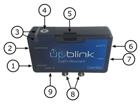
1. Power (Micro-USB connection): You can power UpBlink through the micro USB port. See Section 5. Powering UpBlink for available power configurations.
2. Camera (USB-C connection): This port is used to connect to your GoPro or Sony camera. See section Connecting the Camera to UpBlink for the ports connection information.UpBlink uses a custom cable - do not connect any other USB-C cable to this port as it may damage UpBlink or the camera! If you lose or damage your cable a replacement can be purchased from our website: HERE
3. LED Window: This window provides LED feedback to the user during operation, as well as for firmware updates. See section LED Status Indicator for an explanation of the different LED indicators.
4. WiFi Button: This button is used to toggle UpBlink's WiFi Access Point for programming mode On/Off.
5. Strap Slot: This can be used to tether UpBlink to the camera, accessory, or fixture.
6. Port 1 (2.5mm jack): This port accepts a Wired Remote or other custom trigger. A Wired Remote can be used to turn UpBlink's WiFi Access Point On/Off from a distance, as well as provide LED feedback during operation (if the CamDo LED wired remote is used). UpBlink also has an in-built WiFi button - see item 4 above.
7. USB-A Port: This port is used for firmware updates using a USB thumbdrive. This port’s power output also becomes activated when an upload schedule is triggered, allowing it to be used to power a 3G/4G USB modem to provide an internet connection or power another accessory.
8. Screw Mounts: Two captive nuts (#6-32) can be used to attach the “GoPro Attachment Knuckle” to allow UpBlink to be affixed to the GoPro housing’s pivot mount.
9. Port 2 (3.5mm jack): This accessory port is currently not in use and will become available in future firmware versions.
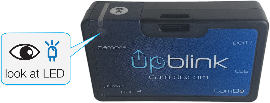
4. LED Status Indicator
UpBlink is equipped with an RGB LED which provides the user with a full range of feedback. While the LED is flashing green UpBlink is NOT in capture mode and schedules are inactive. Below is a list of each LED flash type and what they represent. Under normal operation, the following LED colors/patterns apply:
- Green flashes twice: When UpBlink has been connected to a power source.
- Green flashes once a second: When UpBlink is booting up the WiFi Access Point for programming.
- Green flashes five times: When UpBlink activated the WiFi Access Point signal.
- Green flashes continuously every 5 seconds: Represents that the WiFi Access Point and Programming mode are active and the user is able to connect to the WiFi network broadcast by UpBlink adjusting the programming.
- Cyan flashes once a second: When UpBlink is searching for an internet connection.
- Cyan flashes continuously every 5 seconds: Represents that UpBlink has not yet obtained an internet connection and will only perform the download procedure if an internet connection cannot be established.
- Blue flashes five times: When UpBlink has successfully connected to the router and has an obtained an internet connection.
- Blue flashes continuously every 5 seconds: Represents that UpBlink has an internet connection and is currently performing the download and/or upload procedure.
- Red flashes five times: When UpBlink has failed to connect to the router and/or has failed to receive a connection to the internet.
- Yellow flashes once a second: When UpBlink is ending a process and returning to capture mode.
- Magenta flashes: UpBlink is currently processing a firmware update. DO NOT disconnect power when LED is flashing magenta.
Below is a list of each LED flash type when UpBlink's button is pressed and what they represent.
- Green flash: UpBlink is powered and capture mode is active but not currently triggering the camera (waiting for next scheduled trigger). Holding the the button for three seconds will boot the WiFi AP in programming mode.
- White flash: UpBlink is currently triggering a capture schedule. Holding the the button for three seconds will halt the currently active camera trigger before booting the WiFi AP in programming mode.
- Cyan flash: UpBlink is currently triggering a schedule that requires an upload, but has not yet obtained an internet connection. Holding the the button for three seconds will halt the currently active trigger before booting the WiFi AP in programming mode.
- Blue flash: UpBlink is currently triggering a schedule requires and upload and has obtained an internet connection. Holding the the button for three seconds will halt the currently active trigger before booting the WiFi AP in programming mode.
- Yellow flash: UpBlink is currently in programming mode. Holding the button for three seconds will shutdown the WiFi Access Point and resume capture mode.
- Red flash: UpBlink is using firmware older than v2.5.0 (released Feb1, 2021) and the firmware should be updated. UpBlink is currently triggering a capture schedule. Wait for schedule's trigger to finish before you may activate the WiFi AP in programming mode.
5. Powering UpBlink
UpBlink is powered externally via a micro USB cable plugged into the power port of UpBlink. UpBlink will then manage power to the connected camera via the CamDo custom USB-C cable.

PoE (power over ethernet) can also be used where available to power the UpBlink using a PoE splitter that can supply 5V 2A via a MicroUSB port. Data connections can be supplied using a USB-to-Ethernet adapter on the same line.

5.1 External USB Battery Power
If using an external battery pack, ensure that the battery output has an "Always On" operation. It is important to note that most of the USB battery packs on the market have a standard automatic power saving feature which turns off the battery output if the battery pack is not constantly supplying power to a device (Auto Off feature). If the Sony/GoPro is powered off for more than a few minutes between scheduled triggers, the external battery pack might automatically shutdown due to inactivity. This automatic off power saving mode would result in the camera system becoming unpowered, while the large battery pack still has lots of capacity remaining.

Our battery packs are specially designed for use with the UpBlink controller because they have an Always On power output mode. Our V50 battery packs (pictured above) have the "Always On" mode enabled whenever a USB cable is connected to either of the USB output ports.
6. Connecting the Camera to UpBlink
The UpBlink's USB-C port, labeled "Camera", is used to connect to your GoPro or Sony camera. Follow the section below that matches your camera type.
Note: UpBlink uses a custom cable - do not connect any other USB-C cable to this port as it may damage UpBlink or the camera! If you lose or damage your cable a replacement can be purchased from our website: HERE
6.1 Sony Camera Setup
The Sony camera's battery should remain inside the and default photo capture settings should be adjusted before deployment (See section 9.1 below for Sony capture mode information).
Turn on the camera to set the Sony camera's USB mode to "PC Remote" to allow UpBlink control of the camera. The USB mode selector of the RX0 series can be set through:
MENU → ![]() (Setup3) → [USB Connection] → [PC Remote]
(Setup3) → [USB Connection] → [PC Remote]
For UpBlink to confirm when the camera has captured a file, the Sony's Image Save Destination needs to be set to include "PC".
MENU → ![]() (Setup3) → [PC Remote Setting] → [Still Img. Save Dest.] →
(Setup3) → [PC Remote Setting] → [Still Img. Save Dest.] →
- [PC+Camera] for saving to the camera’s SD card,
- or [PC Only] to skip saving to the camera’s SD card
Select the file format for images to be captured by the Sony camera. Note that although RAW images can be captured, UpBlink will only upload JPG files to the CloudX server.
The captured File Format setting of the RX0 series can be set through:
MENU → ![[camera icon1]](https://cdn.shopify.com/s/files/1/0906/7602/files/sony_menu_shoot1.png) (Quality/Image Size) → [File Format] →
(Quality/Image Size) → [File Format] →
- [JPEG] for saving only JPEG (.JPG) images to the camera’s SD card, which can be tranfered to CloudX.
- or [RAW & JPEG] for saving both RAW (.ARW) and JEPG (.JPG) images to the camera’s SD card. Note the RAW files will not be transfered to CloudX.
- or [RAW] for saving only RAW (.ARW) images to the camera’s SD card. This setting is not recommended for use with CloudX! The use of capture RAW only setting will increment the UpBlink's "sd_photo" counter (status message) but the RAW files will not be uploaded to CloudX.
 The (Quality/Image Size) menu also provides adjustment options for image settings such as aspect ratio and JPEG file size.
To conserve power, set the monitor brightness and volume to the lowest values, which can be set in the RX0 through:
MENU → ![]() (Setup1) → [Monitor Brightness] → [-2]
(Setup1) → [Monitor Brightness] → [-2]
MENU → ![]() (Setup1) → [Volume Settings] → [0]
(Setup1) → [Volume Settings] → [0]
Sony camera battery requirement
The Sony camera's battery must remain inside the camera's battery compartment. UpBlink will maintain a charge to the camera's battery and can reset the camera to restore system functionality should any camera error be experienced.
Sony camera to UpBlink Connection
Connect the included CamDo custom USB-C cable from UpBlink's Camera port to the multi-port (extended microUSB) on the Sony camera. The orientation of the Sony cable must have the checkmark symbol facing the UpBlink label.6.2 GoPro HERO10/11/12 Setup
The GoPro HERO10 and HERO11 cameras require the installation of the GoPro Labs firmware with a QR code to gain control of the Camera's power state. For the UpBlink compatible QR code to function, the GoPro battery MUST be removed from the camera. The default photo and other capture settings should be adjusted from the camera menu before deployment (See section 9.2 below for GoPro capture mode information).
To conserve power, the following settings are automatically set to the GoPro camera from UpBlink:
- Touch display brightness to the lowest 10%
- Screensaver time to the lowest 1 min
- Front display disabled
- Voice control disabled
Installing GoPro Labs
Use one of the following links to download the GoPro Labs firmware for your GoPro camera model:
- HERO13 Black - The HERO13 is compatible but please contact CamDo support to check the latest version (GoPro has been making frequent feature/behaviour changes)
-
HERO12 Black v2.20.70 | March 2024
NOTE: Versions after v2.32.70 are NOT compatible. GoPro has changed the firmware behaviour, breaking functionality and reliability. - HERO11 Black v2.30.70 | March 2024
- HERO10 Black v1.62.70 | May 2024
Use your microSD card to install the GoPro Labs firmware onto your camera.


(or visit this page here: https://gopro.com/en/au/support/hero13-black-product-update/)
Once the GoPro Labs firmware is installed, power on the GoPro camera and point at this QR code.

When the QR code information is accepted by the camera, the GoPro's back display should show an icon of a checkmark and red square overtop of a QR code and beep.

GoPro HERO10/11/12 battery requirement
The GoPro HERO10/11/12 camera battery MUST be removed from the camera. The use of the GoPro battery will prevent UpBlink from gaining control of the GoPro's power state.

GoPro HERO10/11/12 to UpBlink Connection
Connect the USB cable included with the GoPro camera to the GoPro camera, then connect the USB-A end to the CamDo USB-C to USB-A adapter. The USB-C end of the adapter connects to UpBlink's camera port.

Note: While new cables are in production, the current USB adapter is non-reversible. The USB-C cable connection to the GoPro is reversible, however, the correct orientation of the USB-C to UpBlink connection needs to be tested using the power button within UpBlink's manual controls menu.
6.3 GoPro HERO5/6/7/8 Setup
Turn on the GoPro camera to adjust the default settings (See section 9.2 below for GoPro capture mode information). To conserve power, set the touch display brightness to the lowest 10%, the screensaver time to 1 min, and disable voice control. The LED, beep volume, and GPS can also be disabled to conserve additional power if not required. 
GoPro HERO5/6/7/8 camera battery requirement
It is strongly recommended to remove the GoPro battery for reliable long-term deployment. When the GoPro battery is removed, your power supply must be rated for at least 2Amps output at 5Volts. If your power supply cannot provide 2Amps, the GoPro battery can remain inside the camera to provide the additional power require by the camera and UpBlink will maintain a charge to the GoPro battery. However, the use of the GoPro battery will disable the *safety reset feature.
For long term GoPro installations, you must remove the internal battery of the GoPro camera to allow UpBlink to hard reset the camera that can restore system functionality should a GoPro camera error be experienced.

*Safety Reset Feature: Removing the GoPro battery allows for UpBlink to fully manage the power supply to the GoPro camera. Therefore if the GoPro camera becomes unresponsive, such as in the event of a camera crash, UpBlink can pull all power from the GoPro to force a hard reset to restore functionality to the system (similar to pulling and replacing the GoPro battery when the camera crashes). However, if the GoPro battery remains inside the camera, when UpBlink attempts to remove power from the GoPro, the camera will not reset since the GoPro remains powered from the camera battery.
GoPro HERO5/6/7/8 to UpBlink Connection
Connect the included CamDo custom USB-C cable from here to the USB-C port on the GoPro camera. The GoPro cable orientation in not spesific as both ends of the cable are reversible.

7. Connecting to the UpBlink App
UpBlink is programmed entirely through a web interface using its own inbuilt WiFi signal. In order to connect to UpBlink's WiFi signal and use the app, follow these steps:
- Plug a 5Volt micro USB power source into the power port of UpBlink.
UpBlink does not need to be connected to the Sony/GoPro camera to access the UpBlink App to program schedules. UpBlink does need to be connected to the Sony/GoPro camera via the included custom CamDo USB C cable for triggering the camera.
- Press the wifi button on the top of UpBlink (Alternatively, use a button press from a wired remote attached to port 1). Holding the button for three seconds will activate the WiFi signal. While booting up the WiFi Access Point signal the LED will flash green once a second. When the WiFi signal becomes active and available for connection, the LED will flash green quickly five times before continuing to flash green once every five seconds to indicate the WiFi Access Point signal is actively broadcasting.

If the LED illuminates yellow when the button is pressed, UpBlink is currently booting up or broadcasting the WiFi AP signal and holding the button will end the process to resume capture mode. See Section on LED Status for additional LED indications. - With a smartphone or laptop connect to the UpBlink’s WiFi network that will begin with “UpBlink”. The default network name is labeled UpBlink_XXXXXX, where XXXXXX corresponds to the last 6 digits of the MAC address for UpBlink. However, the appended text of the UpBlink WiFi network name can be adjusted through the web interface. If prompted for a password, the default password is:
1234567890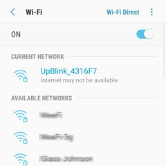
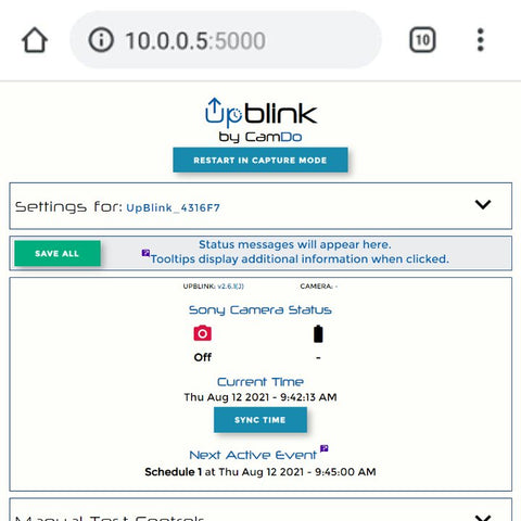
- Now navigate to the URL
http://10.0.0.5:5000with your standard web browser, such as Chrome or Safari. It’s important to include the “http://” as some web browsers require this.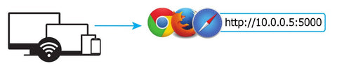
NOTE: Some phones and computers have WiFi settings that will automatically connect to a known WiFi network with the strongest internet signal rather than staying connected to UpBlink. Since connecting to UpBlink's WiFi Access Point network does not provide external internet access, some devices will not stay connected to UpBlink. You might need to temporarily adjust the WiFi settings on your device or remove any saved networks in the area for the period required to set up the new schedule of UpBlink.
7.1 Controlling UpBlink WiFi
UpBlink’s WiFi Access Point signal can be turned on and off by holding down the wifi button on the top of UpBlink for 3 seconds. A wired remote plugged into port 1 can also be used as an alternative to the wifi button.
If the LED illuminates green when the button is pressed, UpBlink is currently in capture mode awaiting the next scheduled trigger and holding the button for three seconds will activate the WiFi AP signal. If the LED flashes white, cyan, or blue, UpBlink is currently processing a scheduled trigger and holding the button for three seconds will end the currently active process before activating the WiFi AP signal. UpBlink flashes the LED green once a second while booting up the WiFi Access Point and then green once every 5 seconds to indicate that WiFi Access Point is actively broadcasting and can be connected to using your smartphone/computer.
See Section on LED Status for additional LED indications.
Once UpBlink has been programmed, the WiFi Access Point must be turned off to resume capture mode. This is done by either pressing the "Restart in capture mode" button from the programming UI, or holding the wifi button down for 3 seconds. When the button is pressed, the LED will flash yellow indicating that the UpBlink busy broadcasting the WiFi Access Point and continuing to hold the button for three seconds will end this active process. While shutting down the WiFi Access Point signal the LED will flash yellow once a second until the WiFi signal has turned off. When the LED is inactive, UpBlink is now in capture mode and will trigger the camera at the programmed schedule times. When in capture mode a short button press will flash the LED green when not triggering the camera and white/cyan/blue if a camera trigger is in process.
7.2 Creating an iPhone shortcut
To make it easy to access the UpBlink app, we recommend creating a shortcut for your smart device.
- After you have connected to the UpBlink WiFi signal with your iPhone / iPad, navigate to
http://10.0.0.5:5000in the Safari web browser. - Click on the small box icon with an arrow pointing up. Then click on add to homescreen.

7.3 Creating an Android shortcut
To make it easy to access the UpBlink app, we recommend creating a shortcut for your smart device.
- After you have connected to the UpBlink WiFi signal with your Android phone, navigate to
http://10.0.0.5:5000in the Chrome web browser. - Click on the small triple dot icon in the top right corner. Then click on “Add to Home screen”.

8. User Interface
The following outlines the key features of the powerful UpBlink web based User Interface (UI).

A. Restart Button: UpBlink's capture schedules are inactive while the WiFi Access Point is broadcasting. Clicking the RESTART IN CAPTURE MODE button will shutdown the WiFi Access Point to activate the schedules in capture mode.
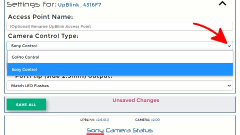
B. Settings Menu: Click the Settings drawer to open the UpBlink's settings menu. This menu provides selection of UpBlink's interfacing ports, including the camera control type (Sony or GoPro) and LED flash indicators. Also included in the settings menu is an optional text field allows you to change the appended text for the network name of UpBlink's WiFi Access Point.
C. Save All: Clicking SAVE ALL will store the settings for all schedules. Important: Be sure to click "SAVE ALL" if any changes are made to the schedules. The Status message box (D) will display if there are unsaved changed to the schedules. If any schedule errors are present, the SAVE ALL button will become grey and disabled, while the problem schedule will become highlighted red. Correct any scheduling errors to enable the green SAVE ALL button.
D. Status Message: This box will display information about your programmed schedules as well as communication status between your viewing device and UpBlink. The box will display Success if your device is connected to UpBlink's WiFi and the controller has accepted the issued command. If your device is no longer connected to UpBlink's WiFi or a communication error has occurred, the disconnection message will be displayed here.
E. Firmware: Displays the current firmware version of UpBlink and the Sony/GoPro camera.
F. Camera Status: Displays information about the Sony or GoPro camera including; the camera's battery life, SD capacity available, and if the camera is powered on with open communication to UpBlink.
G. Camera Time: Displays the time and date used by UpBlink when triggering the programmed schedules. This time and date will be automatically pushed to the GoPro camera when it is triggered by UpBlink making it very easy to keep the system time up to date. The Sony camera time is not synced, although UpBlink's timestamp is used in the file naming (and EXIF data) of any images set to upload. If Cloud uploads are enabled, UpBlink will sync the clock with an NTP server when connected to the internet to ensure the time always remains accurate.
H. Sync Time: Clicking the Sync Time button will push the local viewing device's time, date, and location settings (timezone) to the UpBlink.
I. Upcoming Schedules: Displays the time&date that the next Camera Trigger or Cloud Upload are scheduled to occur.
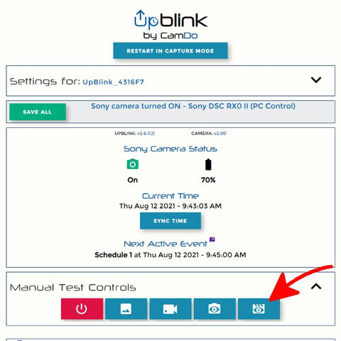
J. Manual Test Controls: This menu can be hidden/revealed by clicking on the drawer to provide a way of manually controlling the camera. These controls are typically only needed to test that the camera is communicating with the UpBlink controller.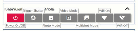
K. Tool-tip: Tooltips are located throughout the UI and clicking on them can provide additional information on the feature.
L. Test Connection Button: Click to verify if an internet connection can be achieved from the network programmed in the Upload Schedule. If connected to the internet, UpBlink will also check if a newer UpBlink firmware version is available.
M. WiFi Network List: After a WiFi search, this drawer will update to contain a list of 2.4GHz WiFi networks located by UpBlink and the signal strength of each network.
N. Upload Schedule: To upload your images to the CamDo CloudX server, click the Upload Schedule drawer to open the schedule to enter your email address, router details, and upload settings. With the GoPro camera, the Upload frequency is set the same way as the capture schedules. With the Sony camera, Upload frequency is programmed in the capture schedule. For image upload capability, you must have either a "USB-Ethernet device" connected to UpBlink's USB port, or a 2.4GHz WiFi router/hotspot signal within the range of UpBlink to provide the internet connection. For more information see section 10. CloudX Uploads.
O. Capture Schedules: These numbered schedules determine when and how the camera will be controlled. Each schedule can be hidden/revealed by clicking on the drawer. Each Schedule is comprised of a Date Window, Day Selector, Time Window, Mode, and Action. Setting these 5 elements will fully define what the camera will do and when it will do it. For more information see section 9. Setting up a Schedule.
P. Example Schedules: Clicking the SET EXAMPLE SCHEDULE button will load the default schedule(s) selected in the dropdown selectors. The loaded example schedules will not become saved until clicking the SAVE ALL button. Refresh the page to reload the schedules that are currently saved to UpBlink's memory.
Q. Logs Page: Clicking the Logs Page link will navigate your browser to the Event Log page, which can be useful for troubleshooting.
9. Setting up a Schedule
- Connect the camera port of UpBlink to the camera using the CamDo USB-C cable. Information about the camera connection and programming for each camera type can be found in section 6. Connecting the Camera to UpBlink.
- Connect the power port of UpBlink to a micro USB power source and wait for the LED to flash green twice, indicating UpBlink is receiving power. The USB power source should be rated for 2Amps output at 5Volts. If using our V50 battery pack, the 'Always On mode' is automatic and no battery configuration is necessary. If using our V44 battery pack, make sure to enable the Always On mode.

- Turn on UpBlink's WiFi Access Point signal used for programming by holding down the wifi button for three seconds.
While booting up the WiFi Access Point signal the LED will flash green once a second. When the WiFi signal becomes active, the LED will flash green quickly five times before continuing to flash green once every five seconds to indicate the WiFi Access Point signal is actively broadcasting. See Section on LED Status for additional LED indications.
- With a smartphone or computer connect to the UpBlink’s WiFi network that will begin with “UpBlink”. The default network name is labeled UpBlink_XXXXXX, where XXXXXX corresponds to the last 6 digits of the MAC address for UpBlink. However, the appended text of the UpBlink WiFi network name can be adjusted through the web interface. If prompted for a password, the default password is:
1234567890
- Open a web browser and navigate to
http://10.0.0.5:5000in the search bar. You will be presented with the following interface. Remember to create a shortcut on your homescreen as described earlier in this manual.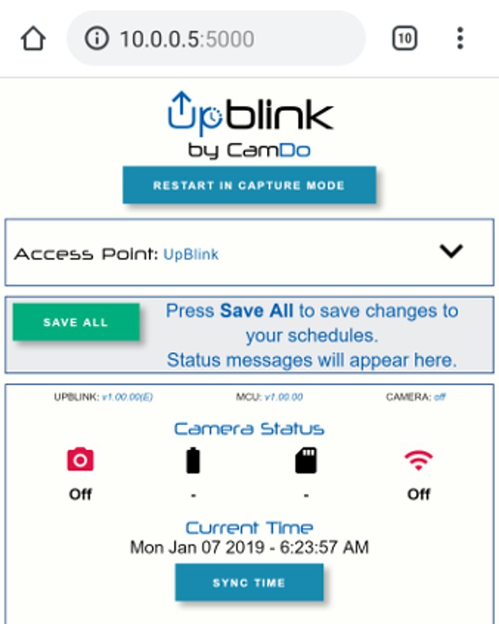
- Click the SYNC TIME button to update the UpBlink's time, date, and location settings with the local settings on your browsing device.

- Open the UpBlink's Setting menu to select your camera control type. The currently selected camera control type is shown in the Camera Status container at the top of the UI.

- Modify a schedule to suit your capture requirements. In this example, we will create a GoPro schedule to take an image every 10 minutes, Monday through Friday, 8am till 5pm. To create the schedule, click on any of the numbered capture schedule drawers to complete the following:
- Set the "Start Date" and "End Date" of your schedule.
- In this example, the start date is set before the current date to begin the schedule immediately. - Click to highlight the days of the week for the schedule to be active.
- As can be seen in the example image below, Mo, Tu, We, Th, Fr are highlighted in blue, indicating they are active capture days. - Set the active "Start Time" and "End Time" for the day's schedule.
- From the “Select a mode” menu, set the type of schedule.
- For "Select your interval", set the length of time between each camera trigger. The minimum interval is 10 minutes.
- An interval of 10 minutes between images is shown in this example. - From the “Select an action” menu, set the type of camera trigger. UpBlink will switch the camera to the selected mode to perform the action. For more information on available Actions, see the next section 9.1 Selecting a Sony Action or 9.2 Selecting a GoPro Action
- in this example, GoPro HERO5 Photo mode is selected.
If overlapping schedules have been programmed and there is a conflict between a start time for any action, the priority is given to the lower numbered schedule. If a schedule is due to be triggered while another schedule is currently performing a task (recording/uploading) the new schedule's trigger will be skipped.
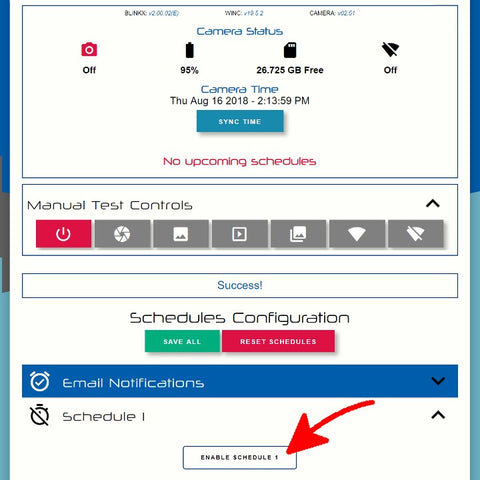
- Once a schedule has been modified, be sure to click the “Enable Schedule” button. A quick way to tell if a schedule is enabled is by the dark blue colour of the drop-down box.

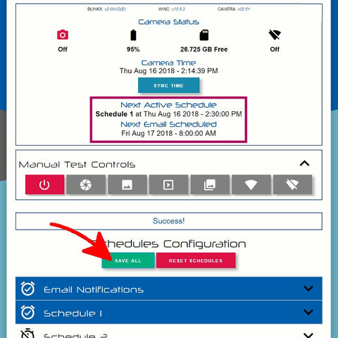
- After making adjustments to the required schedules, click the SAVE ALL button pinned to the top of the UI inside the status message box. The status message box will update to display that the schedules have been saved and the camera status box will update to report when the Next Active Schedule is due to be triggered when UpBlink's programming mode has been disabled and UpBlink resumes capture mode.
If any schedule errors are present, the SAVE ALL button will become grey and disabled, while the problem schedule will be highlighted red. Correct any scheduling errors to enable the green SAVE ALL button to save your schedules. The page will refresh and your next interval scheduled should be shown in the status bar.
- To begin the capture schedules, click the RESET TO CAPTURE MODE button at the top of the UI page to end programming mode. Alternatively, hold the WiFi button on the top of the UpBlink controller for three seconds. While UpBlink is restarting, the LED will flash yellow once per second and the LED will go dark when UpBlink has resumed capture mode.
9.1 Selecting a Sony Action

By selecting the schedule's action, UpBlink preform the selected action and will use the default photo capture settings that have been set from the Sony camera. Ensure to set the desired capture settings from the Sony camera menu before deployment.

Selecting the "Video" & "Camera On" actions require setting the active duration. Note that the duration selected does not include the additional time for the camera to bootup and shutdown when preforming the action. Ensure that your action's duration allows time for the camera to complete the shutdown before the next action is scheduled to be triggered.
For example, a 2minute interval for a 120second video action will only capture footage every 4minutes. This is because the camera is still preforming the current action when the next trigger is scheduled.
Scheduling a "Camera On" action turns the Sony camera on at the scheduled time with no further action, such as switching camera modes or triggering the shutter to capture footage. This can be used for viewing the camera's HDMI output signal rather than recording to the camera's SD card.
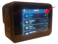
9.2 Selecting a GoPro Action

By selecting the schedule's action, UpBlink will switch the GoPro camera to the selected mode but will use the default resolutions, frame rates, and Protune settings for photo, night photo, burst photo, and video modes that have been set from the GoPro camera. Ensure to set the desired image/video settings from the GoPro camera menu before deployment.

Selecting the "Video" & "Camera On" actions require setting the active duration. Note that the duration selected does not include the additional time for the camera to bootup and shutdown when preforming the action. Ensure that your action's duration allows time for the camera to complete the shutdown before the next action is scheduled to be triggered.
For example, a 2minute interval for a 120second video action will only capture footage every 4minutes. This is because the camera is still preforming the current action when the next trigger is scheduled.
Scheduling a "Camera On" action turns the GoPro on at the scheduled time with no further action, such as switching camera modes or triggering the shutter to capture footage. This can be used for scheduling a USB download window, or for using the camera's HDMI video output signal rather than recording to the camera's SD card.
While UpBlink is typically used to automatically upload footage to CloudX via and internet connection, various options available for manually downloading footage from the GoPro during a time lapse when using our UpBlink time lapse controller are outlined on the following page: https://cam-do.com/pages/how-to-download-your-gopro-time-lapse-footage-with-blinkx
10. CloudX Uploads
For image upload capability (CloudX Pro), you must have a Sony camera (with PC Remote mode), GoPro HERO5 Black camera, GoPro HERO10 Black, or GoPro HERO11 Black camera. When used with other GoPro camera models, UpBlink can trigger capture events but not upload image files and will only upload camera status information (CloudX Lite).
10.1 CloudX Registration and Subscriptions:
Each UpBlink includes a free trial period to the CloudX upload service and remains unregistered until the first connection to our CloudX server. Upon the first successful connection to the CloudX server, the UpBlink will become registered to the CloudX account for the email address used in the programming interface. Once UpBlink is registered to your CloudX account and has begun the free trial period, you will then be able to login to your CloudX account at portal.cam-do.com to manage subscriptions and device settings. If the email address programmed in UpBlink is not yet registered in CloudX, you will be sent a CloudX account activation email within a few minutes.
See our CloudX User Manual for additional information about the upload service: https://cam-do.com/pages/cloudx-manual
10.2 Internet Connection:
To provide the internet connection to the CloudX server, UpBlink requires either a USB-Ethernet device connected to UpBlink's USB port, or a 2.4GHz WiFi router/hotspot signal within the range of UpBlink. If a modem is able to provide internet by broadcasting a 2.4GHz WiFi signal, or has an Ethernet cable output (that can be used with a USB Ethernet adapter), or has a USB output that identifies as an Ethernet device when connected to a USB port, it should be compatible with UpBlink.
When an upload schedule is active, UpBlink’s USB-A port will supply power to the connected USB accessory allowing this port to manage power for a "MiFi USB hotspot router" (broadcasts WiFi signal) or "USB modem" (provides Ethernet signal over USB-data). See below for hotspot options.
The information used by UpBlink to connect to the internet is entered within the "Upload Schedule" drawer. The Upload Schedule is valid and enabled when the drawer is highlighted blue and icon displays a checkmark within a cloud symbol. Ensure you select the "Internet connection" type in the dropdown menu that matches your connection type.

Once your connection information has been entered, it is recommended to use the "Test Connection" button above the "Upload Schedule" to confirm your UpBlink can connect to the internet using the information provided and that you are running the most recent UpBlink firmware available. The internet connection should be tested at the deployment site to confirm internet access is available at the desired location. If there is a weak WiFi signal, you may need a secondary(client) modem placed closer to the camera. If using a USB modem and receiving a weak internet signal, you may need to attach an external antenna to the modem to improve cellular signal, or contact your data provider.

If the test connection was successful, UpBlink will display if the firmware is upto date or download the latest firmware if a newer version is available.
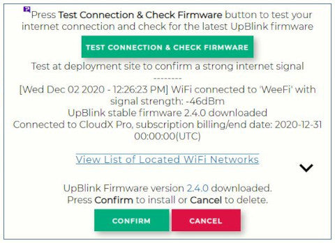
If the internet connection was unsuccessful, UpBlink will display the error message. If attempting a connection to a WiFi network, clicking "View List of Located WiFi Networks" will display a list of the available networks along with their associated signal strength.

10.3 Upload Settings:
All images captured by the GoPro/Sony will be saved to the SD card with the resolution set from camera's menu. However, UpBlink provides the option to upload either the full sized image on the SD card or a smaller compressed image to reduce the upload file size.

For the GoPro HERO5 cameras, the upload mode menu provides the option to either upload all images that have been captured after a specific date, or upload only the latest image that was captured before the upload schedule was triggered.
For the GoPro HERO10/11/12 and Sony cameras, each photo schedule has the option to upload the file and any backlogged files immediately after capture, store the file for upload later (add the file to the backlog), or skip the uploading of the trigger.
The Maximum Upload Duration timeout period is used to ensure the uploading of footage is stopped after a set amount of time has elapsed. The upload timeout can be set for durations as short as two minutes for uploading images between capture intervals. The minimum upload timeout period that is required to complete the upload of all footage will be dependent on the number of photos and router's internet speed.
The Maximum Reconnect Timeout period is the maximum amount of time UpBlink will spend trying to obtain an internet connection. This value can be increased from the default 2minutes if the modem has a slow bootup time or has a "low power sleep mode". This power/data saving mode is typical of modems using mobile SIM data when remaining powered for long periods of inactivity. If the modem is in a low power rest/sleep mode, the modem might be broadcasting the WiFi network so that it can be located and connected to but does not maintain an internet connection until a device has connected. Once a device has connected, the modem might take awhile for the router to "wake up" into the fully powered and internet connected state.
When the Upload Schedule is triggered, UpBlink will download photos from the GoPro camera's SD card before uploading the footage to the CloudX server, whereas the Sony photos are downloaded as they are captured. If an internet connection is obtained, UpBlink will always attempt to upload at least one image per Upload Schedule trigger regardless of the timeout period set. If images have been referenced for upload but have not yet been uploaded to CloudX, the number of backlogged photos will be displayed in the UI. When photos have completed the CloudX upload, the backlogged photos will be removed from UpBlink's memory.
Clicking the DELETE BACKLOG button will remove all backlogged footage from UpBlink as well as clear the reference to the latest indexed file. If using the GoPro HERO5 schedule's Upload All Photos mode, ensure to adjust the cut-off date to avoid re-uploading footage.
10.4 Using a 3G/4G Hotspot:
To upload your images using a 3G/4G hotspot, just plug a suitable USB modem/hotspot/MiFi into UpBlink's USB-A port. UpBlink controls power to the modem via the USB-A port incorporated, therefore only turning on the modem when upload is scheduled to conserve power. We have some suggested modems listed here but generally any 3G or 4G USB stick hotspot that creates a WiFi network or identifies as a USB-Ethernet device will work.
Poor cellular signal?
Many USB modems have one or two ports to attach external antenna that may greatly improve the cell signal of the modem.
 The USB800 & USB730L modems (pictured above) have a TS9 antenna port for connecting an external cellular antenna.
Suitable 3G/4G hotspots
From UpBlink firmware version v2.0.1, we recommend the following cost effective modems. IF THE MODEM HAS NOT BEEN PURCHASED FROM YOUR LOCAL TELCO PLEASE MAKE SURE THE APN SETTINGS ARE CORRECTLY SETUP FOR YOUR TELCO's NETWORK. YOU WILL NEED A COMPUTER AND WEB BROWSER TO DO THIS. YOUR TELCO WILL NEED TO PROVIDE THE CORRECT SETTINGS.
- UFI 4G Modem (sold by CamDo here)
- ZTE MF70A
- Huawei E3372
- Huawei E8372. This modem is rebadged by many telco's around the world and is an excellent cost effective option.
CamDo provide the following guidance to setup the APN to assist however we cannot provide technical support for your modem, please contact your telco.
- Check the modem's user manual for programming information. Some modems may display the programming address and login details on the back or underneath the battery/SIMcard cover plate. The telco's APN may be readily available via a google search.
- Plug the modem into your computer.
- Connect to the modem's WiFi (or Ethernet) network.
- Navigate to modems settings page. (For the E8372 this is 192.168.1.1 or 192.168.8.1 but can vary between regions, please check the user manual)
- If prompted, enter the username and password and click login. (The E8372 default username is 'admin'. Default password is 'admin')
- If you are asked for a PIN, the E8372 modem's default is '0000'. Click 'Apply'. If this does not work, please stop and contact your telco to avoid being locked out from too many incorrect attempts.
- Navigate to the 'Network Settings' page. (For the E8372 click 'Settings' from top menu bar, then click 'Dial-Up' -> 'Profile Management')
- Make sure a Profile exists. If not, click 'New Profile' to create a new profile and enter the details from your telco for your network.
- If the modem settings provides the option to select between Windows/Mac/Linux, select 'Linux'.
- If present, click the save button once your information has been input.
The following specific modem models work for carriers in the US.
- Huawei E3372h-510 (T-Mobile) - USB modem
- Huawei E8372h-517 (AT&T) - wifi hotspot modem
- ZTE MF70/A (T-Mobile) - wifi hotspot modem
- Novatel USB730L Global Modem (Verizon) - USB modem
- Inseego USB8L Global Modem - (Verizon) - USB modem
- Inseego USB800 Global Modem - (AT&T) - USB modem
Any USB powered hotspot that plugs into a USB-A port for power (with no internal battery) and creates a local WiFi network or identifies as a USB-Ethernet device should be suitable, however there are some hotspots that are very power hungry and will not work such as the 'Jetpack' series of modems. UpBlink connects via WiFi or Ethernet to the hotspot to then upload footage. There are many hotspots available in different parts of the world and there are different models being released all the time. We would love to hear which USB modems you have used successfully. USB modems with an internal battery that can be removed may be suitable, but you will have to test if the hotspot automatically turns on when powered via the modems's USB charging port. This is because UpBlink turns power off to the hotspot between upload intervals to save power, so the modem's battery would not consistently recharge and may become depleted.
Unsuitable 3G/4G hotspots
The following modems ARE NOT SUITABLE:
- Alcatel Linkzone Mw40/41 - works with battery removed but too power hungry!
-
Alcatel Linkkey - M2M modem that requires help with different mode switch rules to be implemented
-
AT&T Unit Express 2 - made by Netgear (AC797S)
- ZTE MF910 (sold by Telstra as a Hotspot - the "4GX Wi-Fi Plus") - doesn't work with battery removed
- Huawei E5832 - wifi hotspot but does not work with battery removed
- Huawei E5251 - wifi hotspot but does not work with battery removed
11. Custom Interfacing (FOR ADVANCED USERS ONLY)
UpBlink has a set of stereo audio ports that can be used for custom interfacing to lights, microcontrollers, or other devices. Below outlines the interfacing ports of UpBlink.
This section is for advanced users. You will void any warranty with improper connection to the interfacing ports of UpBlink.
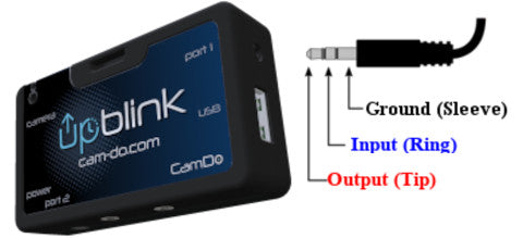
Port Inputs
The port 1 (2.5mm audio jack) of UpBlink is used to trigger the UpBlink WiFi signal by closing contact between the ring and sleeve for 3 seconds and typically used with our wired remote when UpBlink is mounted out of reach. The UpBlink WiFi signal can also be activated by using the push button on the top of the controller. - See the Connecting to WiFi section of the manual for details. The port 1 of UpBlink input does not require additional voltage from the remote for triggering the WiFi signal. The remote only closes contact between 2 input wires (ring and sleeve). Therefore, the button remote can be replaced with a microcontroller or any trigger capable of closing the contact between 2 input pins.
The port 2 (3.5mm audio jack) of UpBlink has no input function. Input functions may become available in future firmware.
Port Outputs
The port 1 is driven high to output 3.3V with a maximum 5mA between tip and sleeve.
The port 2 is driven high to output 5V with a maximum 100mA between tip and sleeve.
Output Modes selectable from UpBlink UI
- Match LED Flashes: The port is driven high to match the LED flashes on the UpBlink controller. This can be used for feedback on the state of the WiFi AP mode when triggering via a wired remote.
- When Camera is ON: The port is driven high when the camera is detected as powered on and communicating with UpBlink. This output can be used for feedback on the status of the camera or for triggering an external device when the camera is on such as a flashlight.
- Off/None: port output is disabled.
11.1 Triggering a high powered device from UpBlink (FOR ADVANCED USERS ONLY)
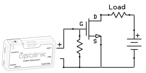
Although the ports of UpBlink only output a low power signal, a solid state relay or a MOSFET circuit can be used as a power switch using the trigger signal provided by the UpBlink's low current outputs to supply power from a high current/voltage source. The switching circuit can be connected between the power source and the external device while only closing the circuit to supply power to the device when UpBlink is providing the trigger signal. The Sparkfun MOSFET Power Control Kit is one of many simple boards with a RFP30N06LE MOSFET capable of switching up to 60V at 30A using a low-current trigger input from our controller boards. Below is an image of an N-Channel MOSFET switching circuit for triggering a load from the output of UpBlink.
NOTE: Connection of custom circuits to the interfacing ports of UpBlink is for advanced users only! You will void any warranty with improper connections to UpBlink.
12. Updating UpBlink Firmware
Occasionally CamDo will release firmware updates for UpBlink to improve performance as well as unlock additional features. Follow this procedure to ensure UpBlink is updated properly. The currently installed UpBlink firmware version is displayed in the top of the programming User Interface. For information about firmware updating and check if you have the most up-to-date firmware, click here.
13. Troubleshooting
Additional UpBlink Troubleshooting information can be found here.
What happens if there is a conflict between schedules?
If overlapping schedules have been programmed and there is a conflict between a start time for any action, the priority is given to the lower numbered schedule. For example, schedule 1 has priority over schedule 2.
If a schedule is due to be triggered while another schedule is currently performing a task (recording/uploading) the new schedule's trigger will be skipped.
What is the UpBlink Event Log?
When UpBlink encounters a problem, an entry is saved into the Event Log. You can access the UpBlink's Event Log page when connected to UpBlink's WiFi and using your web browser to navigate to the URL: http://10.0.0.5:5000/log.html or by clicking the Logs Page link at the bottom of the UpBlink programming interface.
14. Framing the Shoot
14.1 Frame the Shoot with the Sony/HERO10/HERO11 Camera and UpBlink
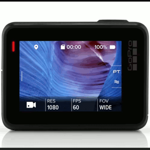
When UpBlink is used with the Sony RX0 camera (or another Sony camera with "PC Remote" USB control mode) or GoPro HERO10/11/12 camera a low resolution view of the camera's field of view can be loaded into the UI via the Manual Controls menu.

The currently selected camera control type is shown in the Camera Status container at the top of the UI.


14.2 Frame the Shoot with the GoPro App
The GoPro App, allows for using the GoPro's WiFi signal to provide a live preview of your camera's view on your smartphone/tablet. This live preview can be helpful to assist with perfectly framing your camera's position for your shoot. Ensure to turn off the GoPro's WiFi after securing the camera to conserve power.
BlinkX cannot activate the WiFi signal of a GoPro that has not yet been paired with the GoPro App.
Camera pairing instructions can be found on GoPro's website here.


Once the perfect shot has been framed, ensure all fasteners are tightened and the enclosure is secure.


Optional: Open the enclosure to turn off BlinkX's WiFi. To conserve power, the BlinkX WiFi signal will automatically turn off after 5minutes of inactivity.