
I’m sure many of you would be familiar with Radio Control (RC) cars - I know I used to love playing around with my ‘Tamiya Madcap’ back in the day.
A customer recently inquired if they could use a Radio Control (RC) transmitter to control the camera shutter on his GoPro camera arrays. They were traveling to the wilds of Kenya and were going to capture various wildlife. In their particular case a motion detector wasn’t going to work and they needed to be able to trigger the cameras manually but from at least 500m away and maybe even 1000m.
This is obviously an interesting use case and piqued my interest, having had an RC car, so I grabbed a cheap Futaba RC transmitter/receiver combo from the local hobby shop and busted out my old cathode ray oscilloscope (yes, cathode ray) to see what was going on at the servo receiver outputs. Futaba is one of the leading brands (and I could get my hands on one quickly) but this should work with most receivers like JR, FrSky, Turnigy, etc out there as they use a standard analog PWM protocol for controlling servos which is the output we are connecting to.
I was able to validate that the outputs were analog PWM based, with a high pulse of between 1200uSec and 1800 uSec depending on the servo position, centred at approx 1500 uSec. The servos interpret the length of the pulse and move to the appropriate position as necessary. Note that there are some fancy bus based systems such as SBUS which are popular - you just want the standard analog PWM outputs. If you have an SBus Tx/Rx combo already, you can purchase a cheap SBUS Decoder to make a PWM signal available.
We will be incorporating the ability to plug an RC receiver directly into our shiny new Blink time lapse controller for GoPro cameras, which will allow our customers various functionality from a long distance but the timeframe for this customer was very short so we looked to a quicker solution as described below, which uses our Bullet controller.
Pololu create some excellent small interface boards, designed to interpret the PWM signals and convert them to digital logic when a certain threshold is reached. It was clear that this could be hooked up with the CamDo Bullet to achieve what was required - camera shutter control at long distances.
The CamDo Bullet controller is a product that enables remote shutter control of your GoPro through a wired remote. The Bullet controllers can be daisy chained together to trigger a whole array of cameras simultaneously, especially useful for a time slice rig (first made famous in The Matrix movie when they featured ‘bullet time’). Being able to use a wired remote is much more reliable and faster than the GoPro WiFi remote and for many people WiFi is simply not an option due to safety concerns (eg at a rocket launch). It also makes it simple to interface to another control system that many of our professional customers in industry utilise (the topic of a future blog post).
We chose to use the Pololu RC Switch with Relay product (there is an assembled and partly assembled version - assembled cuts down your labour effort for an extra $1). This product essentially mimics pressing the wired remote button via radio control, by operating a single-pole, double-throw (SPDT) switch. 
Pololu RC Relay Board
For each set of cameras you are operating, you only need one RC receiver and one Pololu board. You also need one CamDo Bullet board per camera you are controlling (daisy chained).
A little bit of DIY is required but nothing too crazy. If you buy the assembled Pololu product then you don't even need a soldering iron. Just strip some wire and hook up a couple of screw terminals. I was pleasantly surprised as it worked first time for me with no calibration. The Pololu site has a pretty detailed manual for the various modelshere. The following instructions are a combination of content from the Pololu site and the CamDo Application Notes.
Parts required:
- GoPro camera (HERO4 or HERO3+Black/HERO3+Silver)
- 1 x CamDo Bullet (per camera)
- 1 x Pololu RC Switch with Relay (per set of cameras)
- Standard Female-Female servo extension cable
- 1 x RC Transmitter/Receiver combo. I used Futaba for this example but there are plenty of brands out there that utilise the same PWM output format.
- 2.5mm stereo cable

Bullet interface schematic to Pololu RC relay board
Steps:
- Connect the Receiver power supply to the RC Receiver. Typically this could be 6V (eg 4 x AA batteries) or 7.2V supply typically (eg 5 cell NiCd). The receivers typically accept a minimum of 4V and range upwards. Check for your particular brand.
- Pair up your Radio Control Transmitter and Receiver (if required, most will just work out of the box). If your RC receiver/transmitter combo came with a servo, test a channel out and see if the servo moves. If not, you can even just put a multimeter across pins 1 and 3 of the servo output connection and you should see voltage. If you play with the transmitter controls you will see the average voltage move up and down as the PWM signal changes.
- Connect the channel you have just tested between the the RC Receiver and the Pololu board with the Female-Female servo extension cable. Take note of the colour orientation of the cable in the diagram above.
-
Check the indicator LED on the Pololu board to check a valid signal is being read. The LED should blink every second if valid. If valid, play with the connected channel on your receiver - you should hear the relay click and the LED will go solid. It worked straight away for me so hopefully it will be the same for you!If there is no input signal, the LED will blink with a 50% duty cycle and a period of 1 s. In this case, the OUT and GOOD pins will be low. An easy way is to just turn the transmitter off and the LED blink pattern will change as most receivers when they lose signal will just stop outputting a signal. Further details on the various LED states can be foundhere. If you are having trouble, you can try the following steps:
- Check again your servo is working (if you have one).
- Try resetting the board to its default values as describedhere. This is essentially a factory reset and will bring the board back to the most common threshold value.
- If you are still not getting a valid signal, you may need to put the Pololu board into learning mode to calibrate it for your particular receiver. Refer to the Pololu guidehere re putting the board into learning mode andhere re how to use learning mode. Refer to the instructions for the Pololu RC Switch with Relay.
- Take your 2.5mm stereo cable and check which of your bare wires is connected to the Sleeve, Ring and Tip and note down the colour. An easy way is to use a multimeter continuity test.Note that the colours in the diagram above are indicative only and will depend on your cable.One of the cheapest ways to get a cable is to just buy an audio extension cable and cut it to the length you require and strip the ends.
-
Plug into your CamDo bullet and test! The CamDo Bullet Quick Start Guide is located here which gives detailed information but as a quick test try the following, starting with the camera off:
- Turn Camera OnPress and hold the connected RC channel for 1 second (you should hear the relay board click, the LED on Bullet will then illuminate until camera is ON and ready for another command)
- Take Photo (if camera is in Photo mode by default)Press and hold the connected RC channel for 1 second (LED on Bullet will blink while photo is taken)
- Start/Stop Video (if camera is in Video mode by default)Press and hold the connected RC channel for 1 second (LED on Bullet will blink while recording) to start video. Repeat to stop video.
- Turn Camera OffPress and hold the connected RC channel for 3 seconds or longer(LED on Bullet will illuminate until camera has turned OFF)
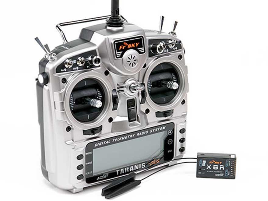
If you have some higher range requirements, you can utilise systems such as the FrSky Taranis system and associated long range receivers or plug in the FrSky transmitter modules straight into JR module compatible transmitters including various JR models and the Turnigy 9X transmitters.There is a good YouTube video here explaining this. These systems are supposed to improve range reliably to 2km or more. You can also change out the stock antennas for a 5 or 7dBi antenna to further assist in range. Depending on the situation, there are plenty of reports of achieving between 5km and 10km but we have not tested these out. There are some great blog posts out there if you are trying to push your range like this one fromBoltRC. Note we can’t recommend a transmitter/receiver combination - you will need to test your particular situation out with your transmitter/receiver of choice.
There are also some amazing add-ons you can buy like theDragonLink orEzUHF from Immersion RC products which use UHF frequencies to extend range out to 40 or 50km which also plug into the back of many transmitters using a standard JR module! If anyone has utilised those systems please let us know!
So there you have it - GoPro shutter control using a radio control system.
We trust this was helpful and as always, if you have any great footage please send it in for a discount on your next order!


