Triggering the GoPro with an Accelerometer
This article relates to our original Time Lapse Intervalometer controller board. Read about how to interface our newer time lapse controller Blink in this blog post.
When Hugh McGregor of the Australian Wildlife Conservancy asked if we could help him with his studies of feral cats by creating a controller for the GoPro camera that would be triggered by an accelerometer just when they pounce on their prey, we jumped on the opportunity. The estimated 15 million feral cats in Australia eat about 75 million rodents and small reptiles every night, some of them endangered species.
Looking at the various accelerometer chips that would interface with our microcontroller, we found the Analog Devices ADXL362 which consumes almost no power when sleeping and had the flexibility to be programmed to wake up when triggered by motion above a user programmable threshold.
We were envisioning programming an interface for the chip, and had already bought some chips to investigate, when Mike Hord at Sparkfun saved us a lot of trouble by combining an ATTiny2313A with ADXL362 on a board they sell as the Wake on Shake.
CamDo Controller Trigger Input
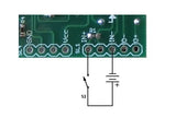 The CamDo Time Lapse Intervalometer includes an optoisolated trigger input which can be operated by any input signal from 3 to 15 volts. Several interface examples are shown in the Application Notes for Advanced Users.
The output of the Wake on Shake board is the battery voltage, so it can be connected directly to the CamDo board input pins, IN+ and IN-.
The newer CamDo boards include a Vcc and ground output which can be used for these accessories. It is connected to the camera battery, so no extra batteries are needed for the accelerometer board.
The MD-003 Motion Detector Board also includes a regulated 5V output, but that was not necessary for this project. It is useful for interfacing accelerometers or other sensors requiring 5 volt power.
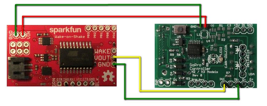
The interface between the Wake on Shake board and the CamDo controller board requires only 4 wires. Two for the power supply and two for the output. Further power saving and one wire could be saved by skipping the optoisolated input and going straight to the MCU input pins, but software changes would also be required to trigger on the opposite signal. This is an option available if we deliver more cat camera controllers to the AWC or other clients.
Adjusting the Accelerometer Parameters
As shown, without modifying the settings on the Wake on Shake board, the camera will be triggered when the accelerometer motion threshold exceeds 150 mg. This is a good level for triggering when an object is picked up and moved.
The ADXL362 can be configured to respond to different threshold levels and combinations, including free-fall, which can also be useful. In this case, we want to not trigger during normal movements and attempt to capture only the violent motion of prey capture by setting a higher trigger threshold.
The acceleration threshold on the Wake on Shake board can be modified using a serial interface connected to the ATTiny processor.
The FT230X USB to serial UART chip is particularly useful for interfacing serial devices because drivers are available for almost all computers. Windows 7 drivers will be automatically installed if the computer is connected to the internet when you first connect the interface. Go to the device manager and in the properties for the newUSB Serial Converter, turn on Install VCP Drivers. Unplug the interface and plug it back in again to automatically install the Virtual Com Port drivers. Instructions for manual installation are on the TDI site, if the automatic install does not work.
Once the drivers are installed, a terminal program, such as the open source PuTTY can be used to talk to the Wake on Shake board. In the serial properties, set the interface to 9600 bps, 8 bits, no parity, 1 stop bit. The Wake on Shake user manual specifies 2400 bps but the board is configured to 9600 bps. One or the other of these will probably change soon. In the session section, select serial. Save the configuration and Open a session to access the Wake on Shake interface.
Pressing Enter will cause the Wake on Shake to report the settings for accelerometer threshold and delay time. The default is 150 mg and 5000 mSec.
To change the accelerometer threshold, enter t followed by the new value and the Enter key. For example,t1000 will change the value to 1000 mg.
To change the delay time, enter d followed by the delay in mSec. As the GoPro controller will handle the true delay time, there is no need to extend it with this setting. Enter d1000 so the Wake on Shake will provide a 1 second trigger signal to the GoPro controller board.
Press Enter to see the new settings.
The Wake on Shake User Guide explains the other settings that can be changed.
For example, the inactivity threshold, which determines when the accelerometer resets and begins waiting for new motion can be changed from its default value of 50mg to 100mg by storing the value 100 in the appropriate memory location. Enter b100 followed by e5 to store 100 in the lower byte of the 2 byte location 4,5. For values above 255, it will be necessary to store the high byte and low byte in the appropriate registers.
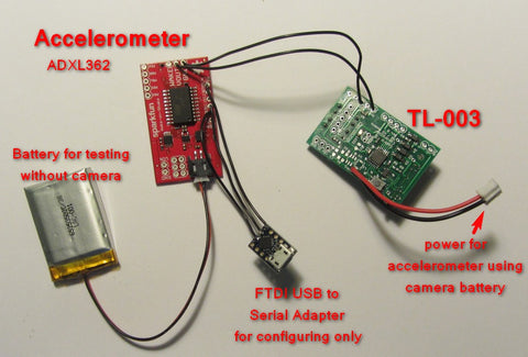
The test setup for programming the Wake on Shake board is shown above. A small LiPo battery can be used to provide power to the board when the camera is not connected.